Session 2: soldering and electronics
circuit basics
At a basic level, a circuit is a circular path through which electricity flows. The first circuits we are going to create today include:
- A source of electricity, for example a battery.
- Something to make use of the electricty, for example an LED.
LED is short for light emitting diode.
- light emitting = something that gives off light when electricity flows through it
- diode = a component that only allows electricty to flow through it in one direction
Test out the diode properties of your LEDs by connecting them to a battery, like in the picture below. If it doesn't light up, turn it around to let the electricity flow through in the other direction.

We cannot always connect an LED directly to a battery, for a few different reasons.
- Sometimes a battery can provide too much voltage or current for the LED, which would cause it to burn out.
- Some colours of LEDs need less voltage to turn on than others, and can stop other LEDs from turning on.
Test this by connecting a blue LED and a red LED at the same time - what happens?
We can get around these issues by using another component, a resistor.
Resistors resist the flow of electricity. We are going to use them to provide less current to an LED, so that, for example, a red LED doesn't use it all up before a blue LED can turn on!
To work out how much resistance a resistor is providing, they have coloured stripes on them. For this workshop, we have given set values, but if you are interested in knowing more, have a look at this resistor colour code calculator.
printed circuit boards
A printed circuit board, or PCB for short, has the wires of the circuit inside the board. Holes are added for you to put your components into, and are designed to be soldered.
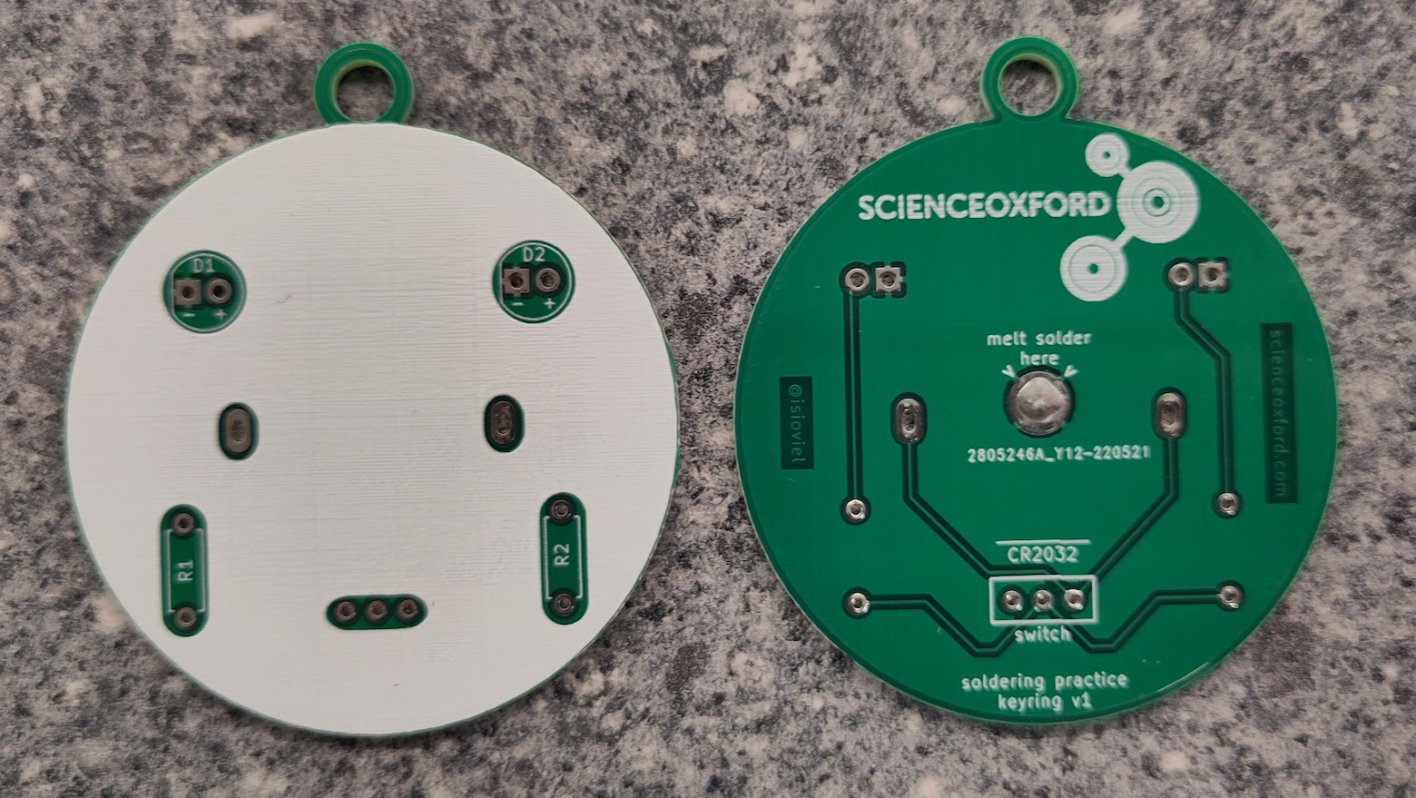
Look careful at the PBC you have been given - can you work out where the LEDs, resistors and battery will go?
The extra component you have been given is a switch. This either lets electricity flow, or stops the electricty flow, depending on which way you push it.
See if you can spot where the wires inside the board are, and trace the connections between components.
soldering safety
A soldering iron heats up to approximately 300°C - it is very important that you are careful when using the iron, to reduce the risk of burning yourself and other people around you.
The most important rule, is to put the iron back in the holder when you are not using it. Never leave it resting on your work surface.
If you burn yourself, carefully put the iron away (or ask someone to do this for you), tell an adult what has happened, and run the burn under cold water for at least 10 minutes.
how to solder
Kitronik have a great 10-step guide to soldering, which includes pictures of good joints, and show some common mistakes.
For your practice soldering, you will make a keyring or pendant. It is a basic circuit to turn two LEDs on or off with the switch.
Step-by-step instructions for soldering the practice boards are provided here:
Once you have finished the soldering, you can use markers to decorate it.
If you would like more practice before soldering your robot's power board, we have other practice boards for you to choose from.
understanding your robot power board
The board you are going to assemble today controls the power to different parts of the robot.
Your robot will be powered with a 9V battery, but this is too high a voltage for the micro:bit (which needs 3.3V), and for the ultrasonic sensors (which need 5V).
This board uses voltage regulators to reduce the voltage provided by the battery in different ways, giving you options for how to connect different components.
It is a bit like having three circuits connected together, and we are using different colours to indicate how much voltage each circuit uses.
Red = ~9V
anything plugged in here uses the maximum voltage given by the batteries, used for the motors
Blue = 5V
used for the ultrasonic distance sensors
Yellow = 3.3V
used for the micro:bit
As you solder your board, pay attention to the colours of the components you are adding, to make sure they go in the correct section. This will make using and troubleshooting your board much easier in the future.
The picture below shows the components you will be adding, and what colour-coded section of the board they apply to.
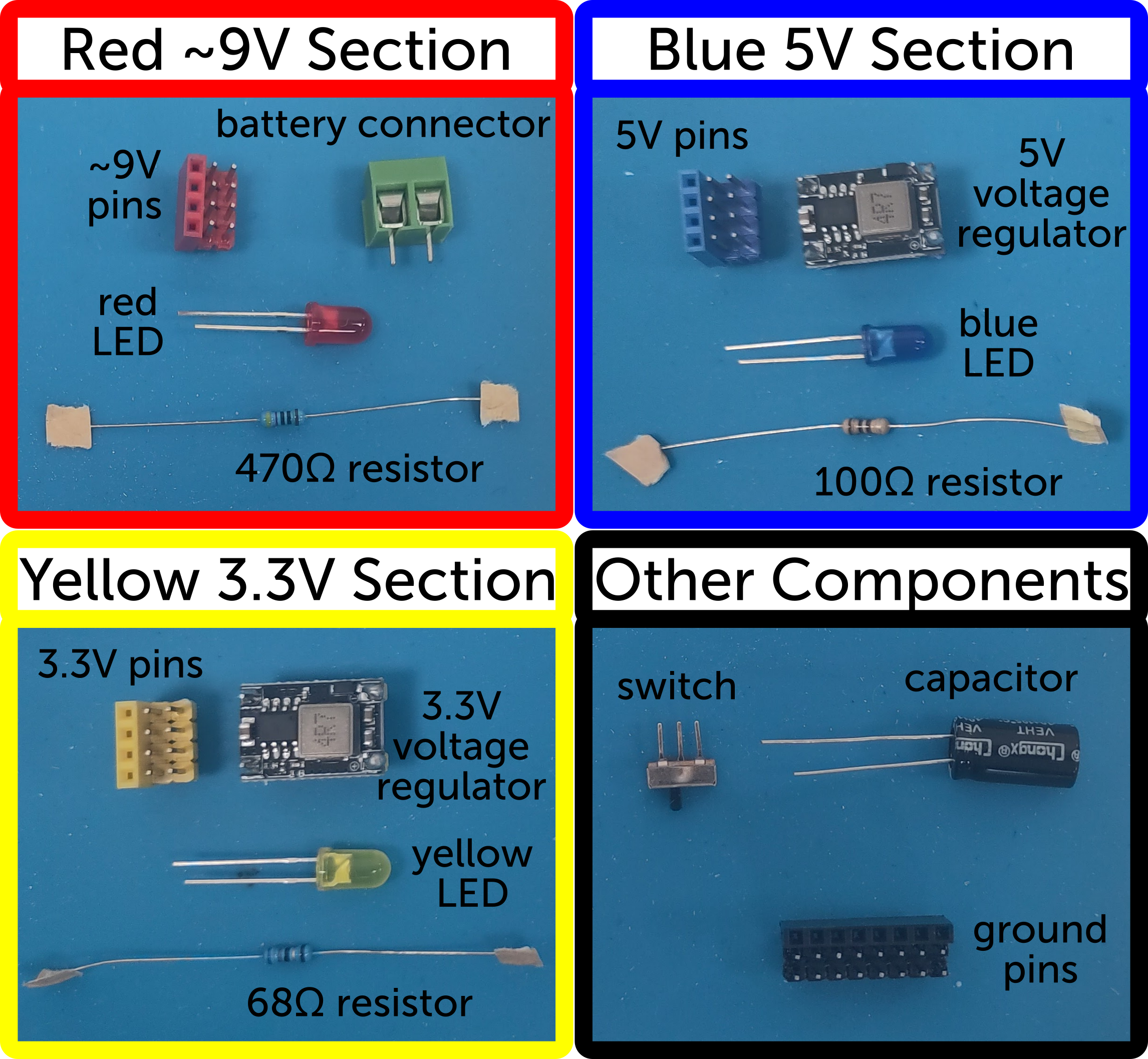
Red ~9V Section
- Battery connector
- Set of red pin headers, so you can connect wires to the ~9V supply
- Red LED, to give a visual reference that the battery is working
- 470Ω resistor, to make sure the red LED works correctly
Blue 5V Section
- 5V voltage regulator, to provide a consistent 5V supply to this section
- Set of blue pin headers, so you can connect wires to the 5V supply
- Blue LED, to give a visual reference that the 5V regulator is working
- 100Ω resistor, to make sure the blue LED works correctly
Yellow 3.3V Section
- 3.3V voltage regulator, to provide a consistent 3.3V supply to this section
- Set of yellow pin headers, so you can connect wires to the 3.3V supply
- Yellow LED, to give a visual reference that the 3.3V regulator is working
- 68Ω resistor, to make sure the yellow LED works correctly
Other Components
- Switch, so you can turn the board on and off
- Capacitor, to help keep things running smoothly when your robot is drawing lots of power
- Set of black pin headers, so you can connect wires to ground (negative)
soldering your robot power board
Step-by-step instructions for soldering your robot board, are provided here:
Do not worry if you do not have time to solder the whole board during the workshop, we will finish it off ready for you to use in your robot.