Follow the instructions below to connect your switch to your robot, then program your robot to react to it being pressed!
If you have not yet soldered the pin connectors onto your robot, click here.
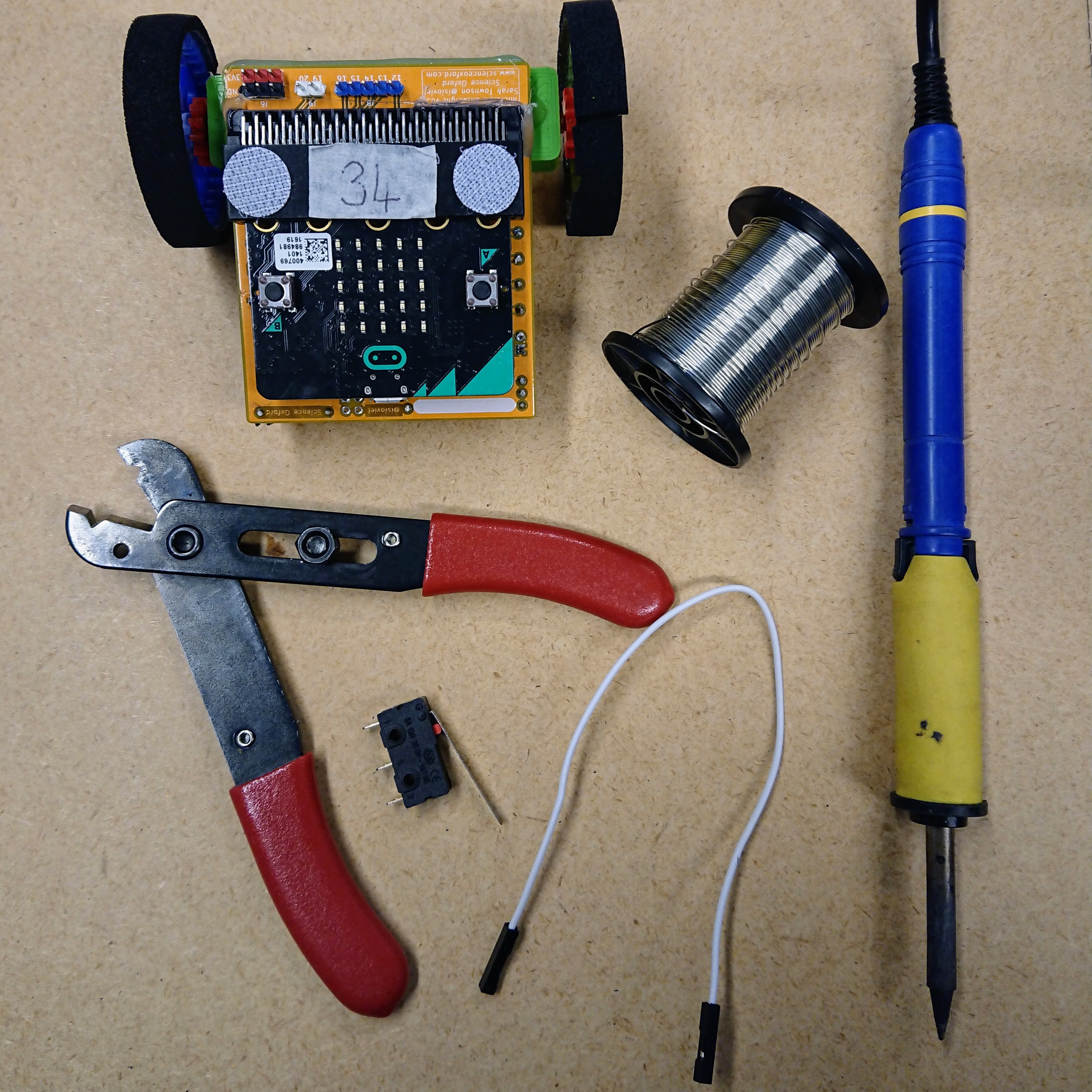
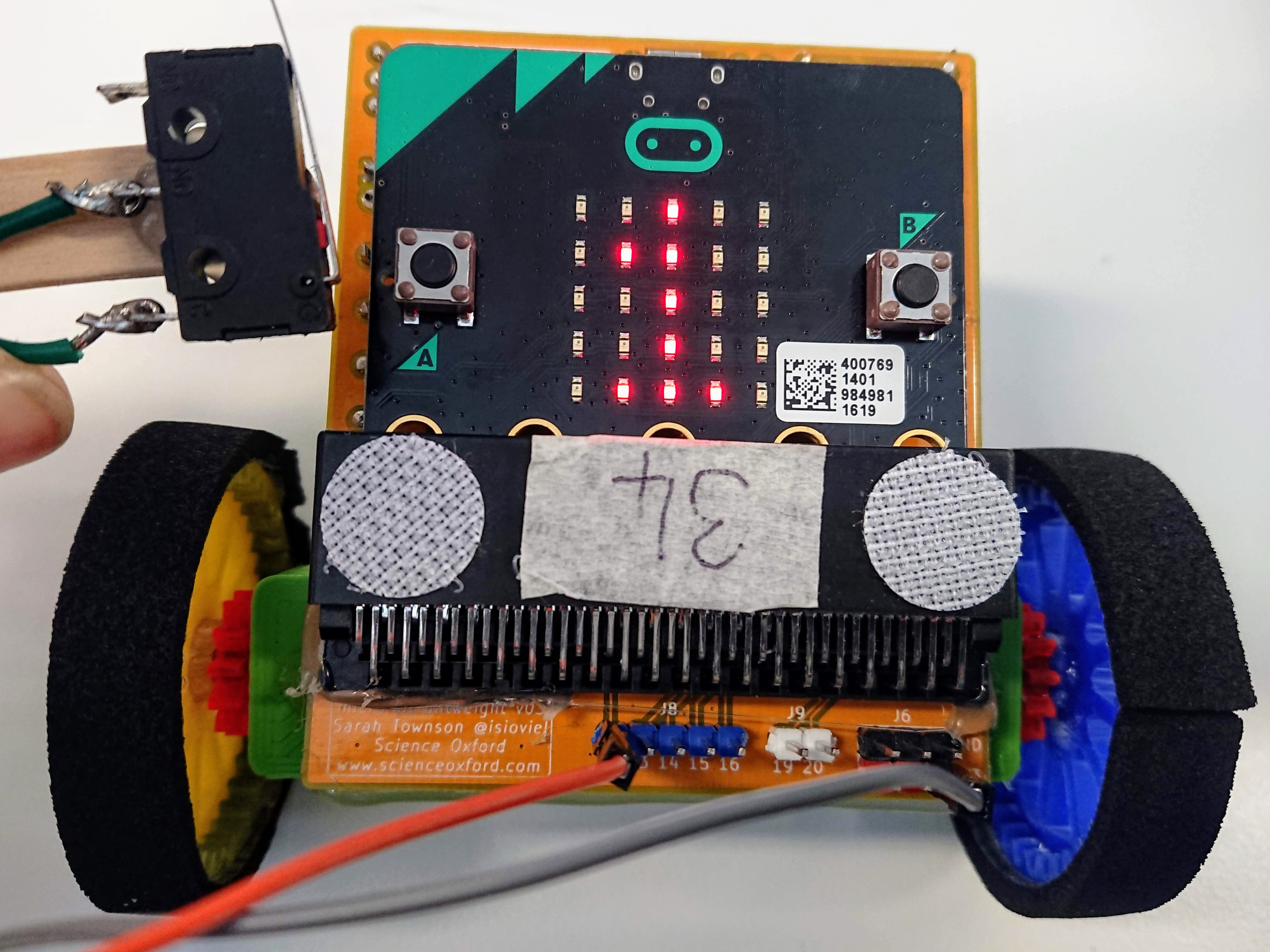
Step 1: collect your supplies
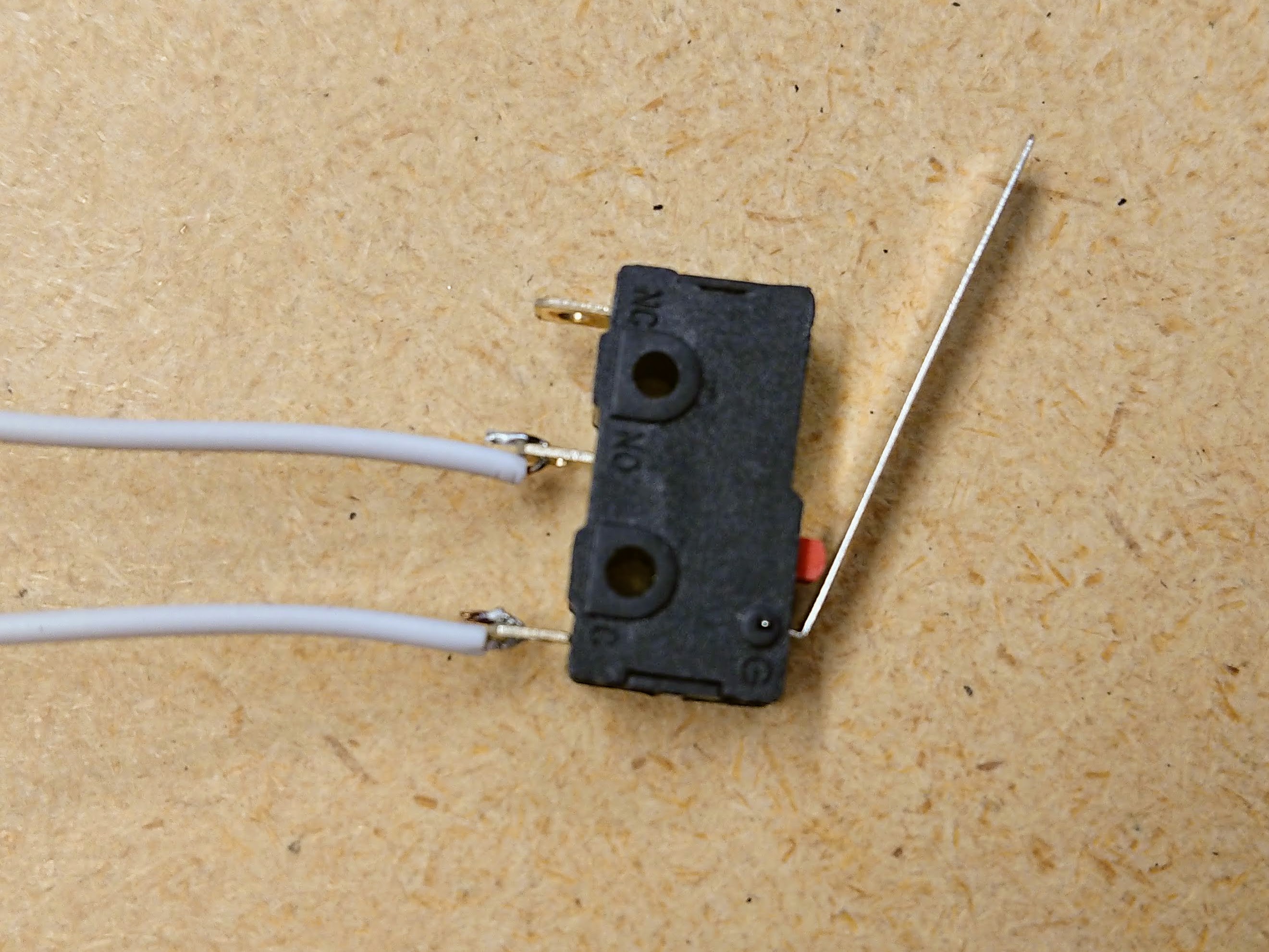
Step 2: solder wires to your switch.
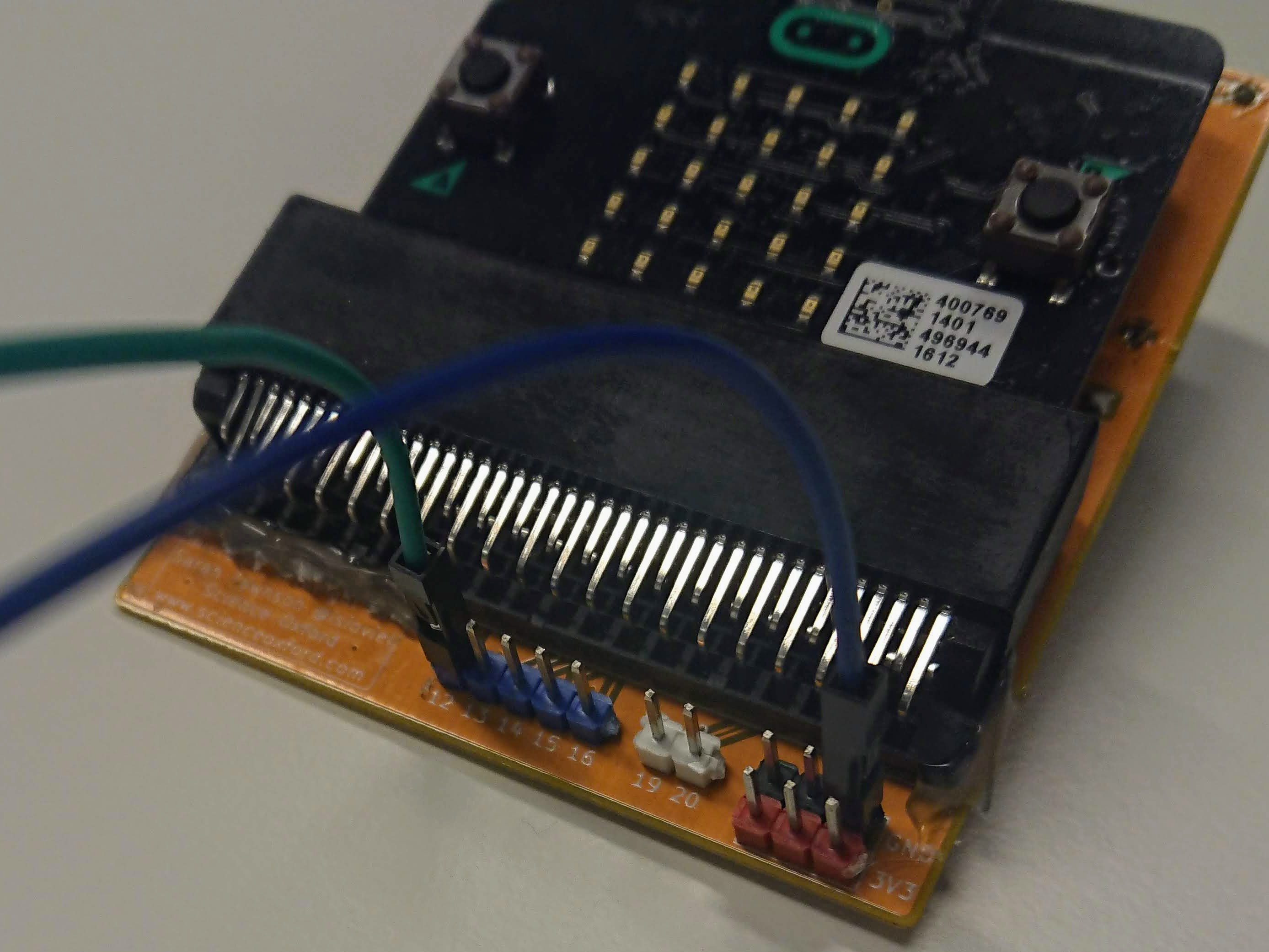
Step 3: connect the wires to your robot
Notes: information about the components
Step 1: testing your switch
Open your robot program (if you were at Robocamp, click here to find yours)
You are going to add new code near the top of your program, underneath import radio and above radio.config.
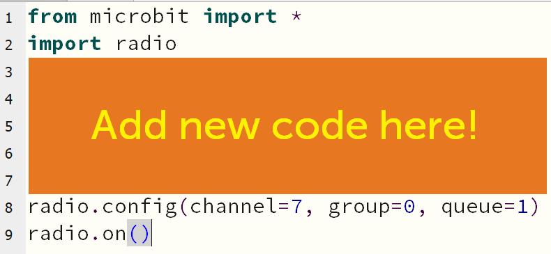
In this spot, add the following code:
switch = pin12.read_digital()
display.show(switch)
sleep(1000)
Do you get a 0 showing on your screen?
What do you see if you run the code for the first time while holding down the switch?
Unplug your robot from the computer to make it easier to test - you can restart the code by turning it off and on again.
You should get 0 when the switch is not pressed, and 1 when it is pressed. If not, check your code and your wiring.
Step 2: the logic of a bumper switch
In this example, we are going to make your robot stop moving when the bumper switch is pressed, even if you continue to move your joystick.
You can then improve this code by, for example, allowing you robot to move backwards to move away from the obstacle.
Plug your micro:bit back into the computer, and remove the three new lines of code you added at the start of your program.
At the bottom your program, in your while True loop, ask the micro:bit to check the status of it's switch, as well as doing everything else.
while True:
    switch = pin12.read_digital()  # this is your new line!!
    message = radio.receive()
The next part of your code tells the micro:bit to turn on the motors if the message is not None. Before doing this though, you want to check if the switch has been pushed or not!
From your checks earlier, you know that switch is 1 if it has been pushed, so you can edit the code to look like this:
    if message is not None:
        message = message.split()
        if switch == 1:
            display.show(Image.NO)
        else:
            drive(int(message[0]), int(message[1]))
Now, if the switch is pressed, the robot will show an image instead of turning on the motors.
Test it out!
Step 3: expanding this code
Instead of stopping the robot completely, you can check if the joystick is trying to move it in a forwards or backwards direction.
Some hints:
int(message[0]) is the value being given to the left wheel.and and or are valid commands in python.> means greater than, and <= means less than or equal to.See if you can combine these things to make your robot behave how you want.
Step 4: fixing the switch to your robot
Think about where your bumper needs to go, and what you want it to detect.